Connecting to IR RGB Controller with 4 Pin Connector
Solder Connection - to wires on end of Strip
In order to connect to the output of our RGB IR controllers, you must use a 4 pin connector. You can connect it to the LED strip by soldering it to the wires on the end of the LED strip (as depicted here), or by soldering it directly to the strip’s solder pads. If you do not know how to solder, simply ask us to solder the 4 pin connector on for you when you are ordering.
−− • • −− • • −− • • −− • • −− • • −− • • −− • • −− • • −− • • −− • • −− • • −− • • −− • • −− • • −− • • −− • • −− • • −− • • −− • • −− • • −− • • −− • • −− • • −−
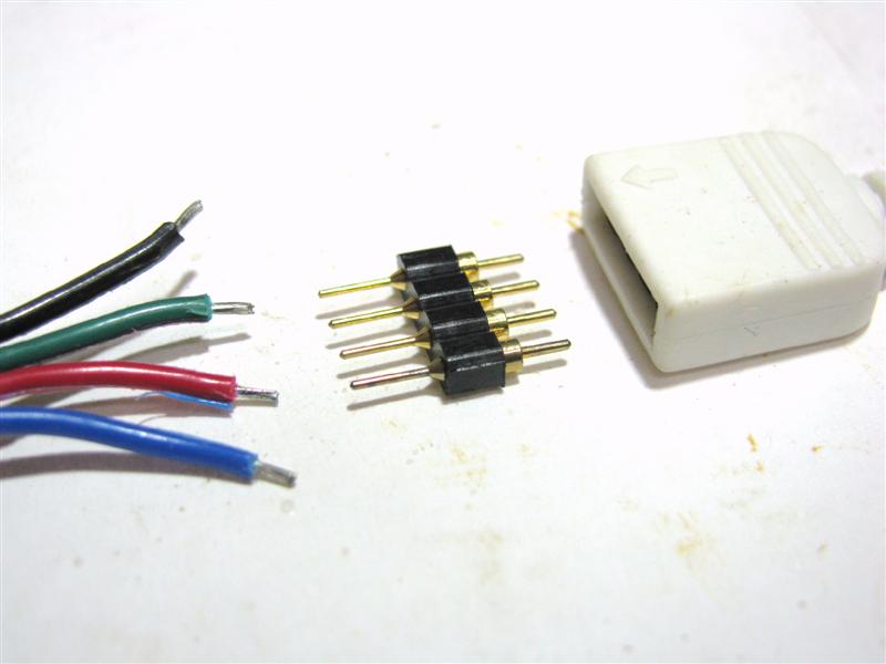
Step #1: Make sure that your RGB LED strip has wires on the end. The pins on the left (as pictured) will be soldered to the stripped wires of the LED strip, and the pins on the right (as pictured- with the thicker cylindrical base) will plug into the IR receiver.
|
|
|
|
−− • • −− • • −− • • −− • • −− • • −− • • −− • • −− • • −− • • −− • • −− • • −− • • −− • • −− • • −− • • −− • • −− • • −− • • −− • • −− • • −− • • −− • • −− • • −−
Step #2: Insert your 4 pin connector into the IR receiver. This prevents the pins from bending while soldering. Pre tin the pins sticking out with Rosin-Cor solder. In addition, make sure that the wires attached to the flexible LED strip are stripped approximately 1/8” and pre tinned.
|
|
|
−− • • −− • • −− • • −− • • −− • • −− • • −− • • −− • • −− • • −− • • −− • • −− • • −− • • −− • • −− • • −− • • −− • • −− • • −− • • −− • • −− • • −− • • −− • • −−
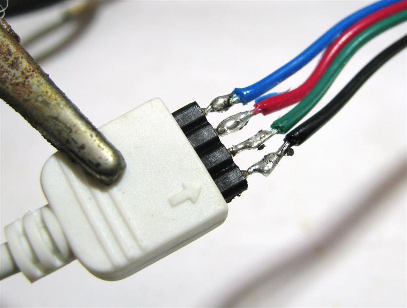
Step #3: Solder the 4 pins to the stripped wires, keeping the wires in the same order. It is helpful to use a clip to support your connections while soldering.
|
|
|
−− • • −− • • −− • • −− • • −− • • −− • • −− • • −− • • −− • • −− • • −− • • −− • • −− • • −− • • −− • • −− • • −− • • −− • • −− • • −− • • −− • • −− • • −− • • −−
Step #4: Cover the connection with hot glue and/or heat shrink tubing.
|
|
|
|
|
|
−− • • −− • • −− • • −− • • −− • • −− • • −− • • −− • • −− • • −− • • −− • • −− • • −− • • −− • • −− • • −− • • −− • • −− • • −− • • −− • • −− • • −− • • −− • • −−
Step #5: Once the heat shrink tubing has cooled off, you can test your IR controller. If it does not work, simply pull out the 4 pin connector, reverse it, and put it back into the IR receiver.
|
|
−− • • −− • • −− • • −− • • −− • • −− • • −− • • −− • • −− • • −− • • −− • • −− • • −− • • −− • • −− • • −− • • −− • • −− • • −− • • −− • • −− • • −− • • −− • • −−
−− • • −− • • −− • • −− • • −− • • −− • • −− • • −− • • −− • • −− • • −−


